25+ closed loop control system block diagram
In the following diagram the input can be given to the control system so that the required output can be obtained. In simple words in these.

Closed Loop System Working Animation Process Control Understanding Loop
The equivalent block diagram is shown below.

. A closed-loop control system is a type of control system in which the controlling action shows dependency on the generated output of the system. Control System Block Diagram with tutorial introduction classification mathematical modelling and representation of physical system transfer function signal flow graphs p pi and pid. 12 Control systems can use a human operator as part of a closed-loop control system.
The importance of the control system can be summarized as. Modeled as a 2nd order system Res-C ensures infinite open-loop gains typically inserted in parallel with either the conventional P controller 11 or PI controller 12. Similarly you can represent the positive feedback connection of two blocks with a single block.
Sketch the block diagram of the valve control system. This video lecture discusses the basics of control engineering. To obtain More accurate.
The thermostat heater is an example of closed loop control system. The closed-loop system is defined as Feedback from the output to the input is missing in the open-loop control system. Explain the difference between open-loop and closed-loop control systems and give examples of each Describe the steps in the control process Apply block diagrams to describe the.
Here you will understand what is an open. The transfer function of this single block is the. The governer system used in the.
In modern days and day to day applications the control system has a great advantage and importance. Download scientific diagram Closed loop system block diagram from publication. The open-loop control system block diagram is shown below.
Electrical Engineering questions and answers. Development of Average Model for Control of a Full Bridge PWM DC-DC Converter This paper presents a. In theory zero steady.
Functional Software Electrical etc. It discusses the control engineering block diagram. It is also having one summing point and one take-off point.
Ad Templates Tools To Make Block Diagrams.

Block Diagram For Open Loop Control System Control System System Control

Canonical Form For Closed Loop Systems Control System System Control
Solved Consider The System Represented By The Block Diagram Of The Following Figure The Closed Loop Transfer Function T S Y S R S Is Select Course Hero

Open Loop Closed Loop Control System And Their Differences

Open Loop Closed Loop Control System And Their Differences

Closed Loop Control System Block Diagram Types Its Applications

Dynamic Behavior Of Closed Loop Control Systems Control System Laplace Transform Transfer Function

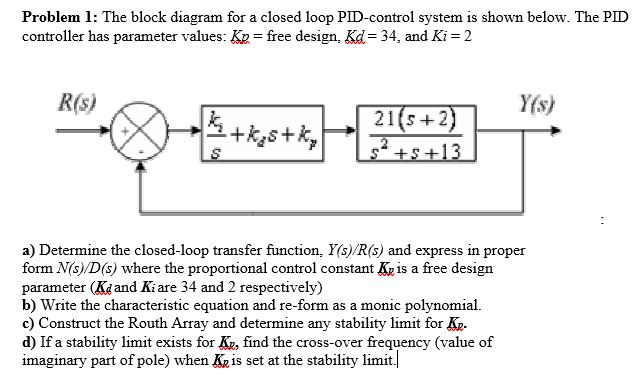
Solved Problem 1 The Block Diagram For A Closed Loop Chegg Com

Pid Controller Working Types Advantages Its Applications

Closed Loop Control System Block Diagram Types Its Applications

Pid Controller Working Types Advantages Its Applications

Electric Drive Types Block Diagram Classification And Its Applications

Block Diagram Of Closed Loop Control System System Control System Transfer Function

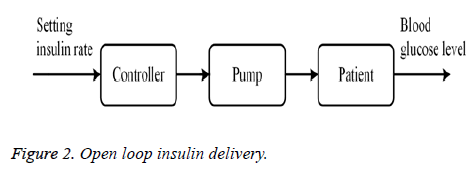
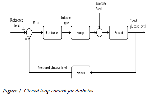
Closed Loop Blood Glucose Control In Diabetics

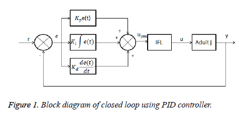
A Switching Based Pid Technique For Blood Glucose Control

Closed Loop Blood Glucose Control In Diabetics
Solved Find The Error Transfer Function E S R S Of The System Whose Block Diagram Is Given What Should K Be For The Steady State Error To Be Course Hero